The multi-projector-mapper (MPM) is an open-source software framework for 3D projection mapping using multiple projectors. It contains a basic rendering infrastructure, and interactive tools for projector calibration. For calibration, the method given in Oliver Bimber and Ramesh Raskar’s book Spatial Augmented Reality, Appendix A, is used.
The framework is the outcome of the “Projections of Reality” cluster at smartgeometry 2013, and is to be seen as a prototype that can be used for developing specialized projection mapping applications. Alternatively, the projector calibration method alone could also be used just to output the OpenGL projection and modelview matrices, which then can be used by other applications. In addition, the more generic code within the framework might as well serve as a starting point for those who want to dive into ‘pure’ Java / OpenGL coding (e.g. when coming from Processing).
Currently, at ETH Zurich’s Future Cities Laboratory we continue to work on the code. Among upcoming features will be the integration of the 3D scene analysis component, that was so far realised by a separate application. Your suggestions and feedback are welcome!
1 Source Code Repository @ GitHub
The framework is available as open-source (BSD licensed). Jump to GitHub to get the source code:
https://github.com/arisona/mpm
The repository contains an Eclipse project, including dependencies such as JOGL etc. Thus the code should run out of the box on Mac OS X, Windows and Linux.
2 Usage
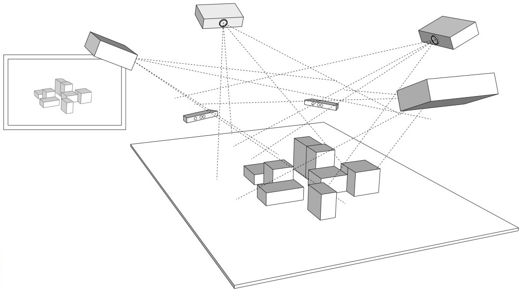
The framework allows an arbitrary number of projectors – as many as your computer allows. At smartgeometry, we were using an AMD HD 7870 Eyefinity 6 with 6 mini-displayport outputs, where four outputs were used for projection mapping and one as control output:
2.1 Configuration
The code allows opening an OpenGL window for every output (for projection mapped scenes, windows without decorations are used, and they can be placed accordingly at full screen on the virtual desktop):
public MPM() {
  ICalibrationModel model = new SampleCalibrationModel();
  scene = new Scene();
  scene.setModel(model);
  scene.addView(new View(scene, 0, 10, 512, 512,
    "View 0", 0, 0.0, View.ViewType.CONTROL_VIEW));
  scene.addView(new View(scene, 530, 0, 512, 512,
    "View 1", 1, 0.0, View.ViewType.PROJECTION_VIEW));
  scene.addView(new View(scene, 530, 530, 512, 512,
    "View 2", 2, 90.0, View.ViewType.PROJECTION_VIEW));
  ...
}
Above code opens three windows: one control view (which contains window decorations), and two projection views (without decorations). The coordinates and window sizes in this example are just samples and need to be adjusted for a concrete case (i.e. depending on virtual desktop configuration).
2.2 Launching the Application & Calibration
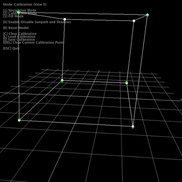
Once the application launches, all views show the default scene. The control view in addition shows the available key strokes. Pressing “2” switches to calibration mode. The views will now show the calibration model, with calibration points. Note that in calibration mode, all projection views will blank, unless their window is activated (i.e. by clicking into the window).
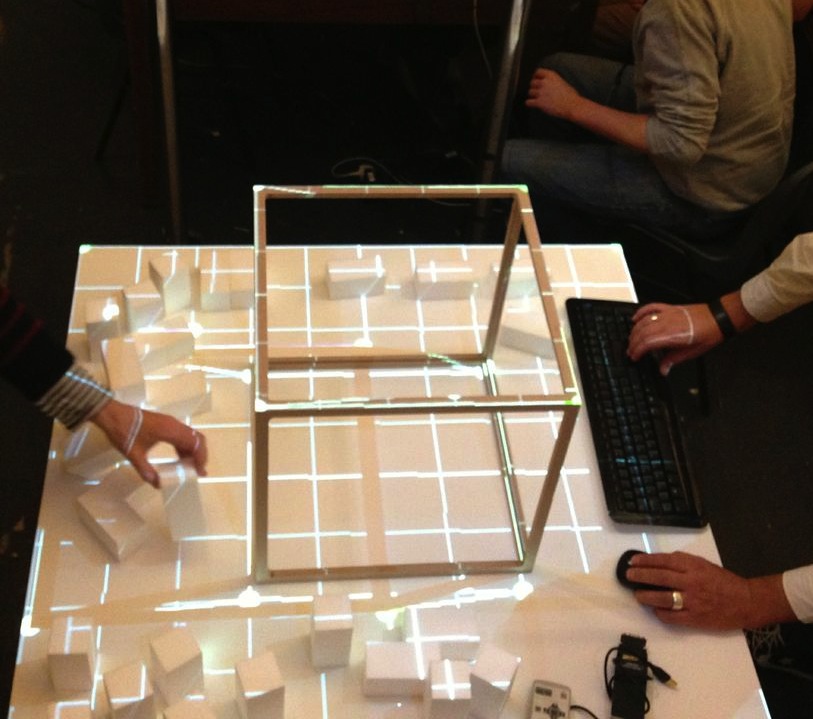
For calibration, 6 circular calibration points in 3D space need to be matched to the their physical counterparts. Thus, when using the default calibration model, which is a cube, a physical calibration rig corresponding to the cube needs to be used:
The individual points can now be matched by dragging them with the mouse. For fine tuning, use the cursor keys. As soon as the 6th point is selected, the scene automatically adjusts.
For first time setup, there is also a ‘fill mode’ which basically projects a white filled rectangle (with a cross hair in the middle) for each projector. This allows for easy rough adjustment of each project. Hit “3” to activate fill mode.
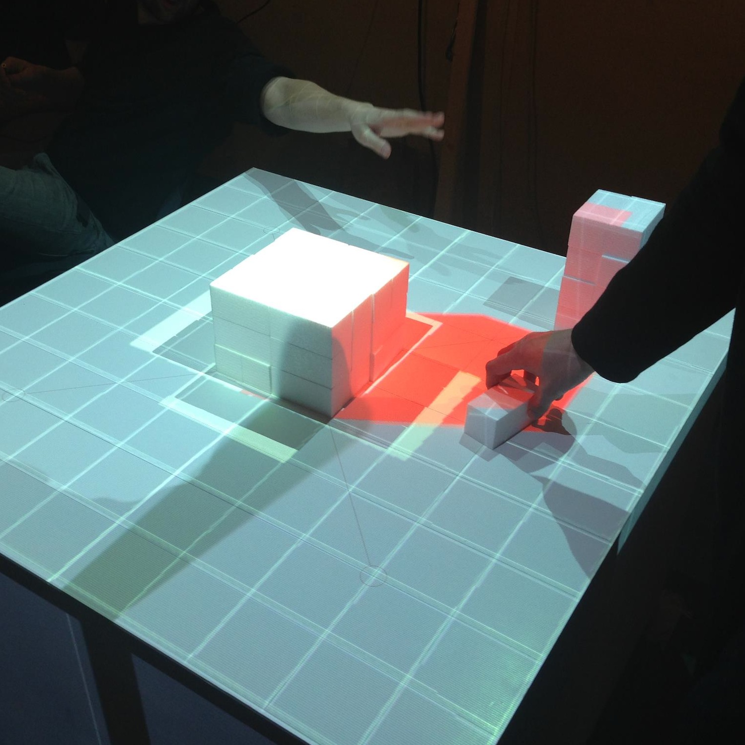
Once calibration is complete, press “S” to save the configuration, and “1” to return to navigation / rendering mode. On the next restart, press “L” to load the previous configuration. When in rendering mode, the actual model is shown, which by default is just a fake model, thus a piece of code that is application specific. The renderer includes shadow volume rendering (press “0” to toggle shadows), however the code is not optimised at this point.
Note that it is not necessary to use a cube as calibration rig – basically any 3D shape can be used for calibration, as long as you have a matching 3D and physical model. Simply replace the initialisation of your ICalibrationModel with an instance of your custom model.
The following YouTube video provides a short overview of the calibration and projection procedure:
3 Code Internals and Additional Features
The code is written in Java using the JOGL OpenGL bindings for rendering, and the Apache Commons Math3 Library for the matrix decomposition. Most of the it is rather straightforward, as it is intentionally kept clean and modular. Rendering to multiple windows makes use of OpenGL shared contexts. Currently, we’re working on the transition towards OpenGL 3.2 and will replace the fixed pipeline code.
In addition, the code also contains a simple geometry server, basically listening via UDP or UDP/OSC for lists of coloured triangles, which are then fed into the renderer. Using this mechanism, at smartgeometry, we build a system consisting of multiple machines doing 3D scanning, geometry analysis and rendering, by sending geometry data between them using the network. Note that this is prototype code and will be replaced with a more systematic approach in future.
4 Credits & Further Information
Concept & projection setup: Eva Friedrich & Stefan Müller Arisona. Partially also based on earlier discussions and work of Christian Schneider & Stefan Müller Arisona.
Code: MPM was written by Stefan Müller Arisona, with contributions by Eva Friedrich (early prototyping, and shadow volumes) and Simon Schubiger (OSC).
Support: This software was developed in part at ETH Zurich‘s Future Cities Laboratory in Singapore.
A general overview of the work at smartgeometry’13 is available at the “Projections of Reality” page.


